

Flexible risers have become a common feature in oil and gas offshore field developments since they were first deployed in the 1970s. Their popularity stems from their flexibility, longevity, relative ease of installation and general resistance to corrosion.
But they are not immune to corrosion and understanding its cause is key to adjusting insurance claims accurately when failure occurs. Here, with the assistance of experts from Minton Treharne Davies (MTD) we explore the steps that a forensic engineer would typically follow to establish the cause of corrosion to steel armour wires in a flexible riser.
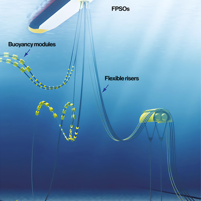
Typical application of a flexible riser with an FPSO (Floating, Production, Storage and Offloading Unit)
Typical anatomy of a flexible riser
Flexible risers have a multi-layer design as detailed below.
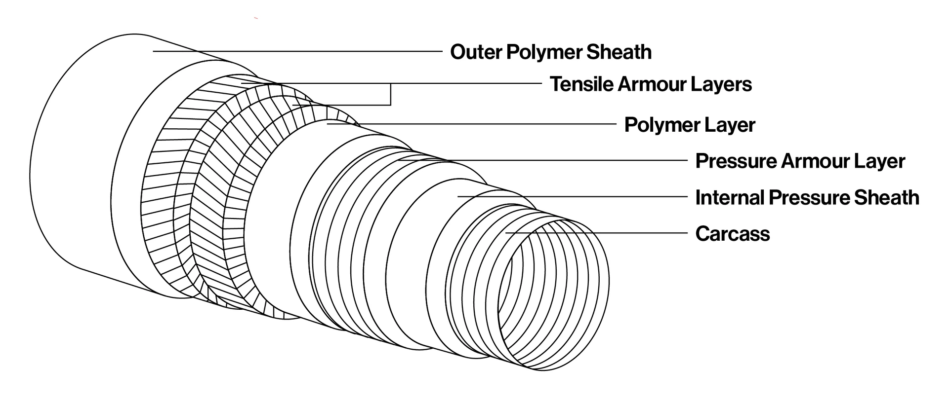
Outer polymer sheath - used to protect against penetration of seawater, corrosion, abrasion, and mechanical damage. This layer also keeps the tensile armours in position after manufacture.
Tensile armour layer - a structural layer which consists of helically wound flat metallic wires that are typically counter laid in pairs and generally made from carbon steel. They totally or partially sustain tensile loads in the riser.
Internal pressure sheath - a polymer sealing layer that is extruded over the carcass. It is exposed to the fluid in the bore.
Pressure armour layer - also referred to as the hoop layer, or zeta layer. It increases the resistance of the flexible pipe to internal and external pressure. This layer typically consists of an interlocked metallic construction, C-shaped metallic wires and/or metallic strips made of carbon steel.
Carcass - an interlocked metallic construction used as the innermost layer to prevent collapse of the internal pressure sheath due to pipe decompression, external pressure, tensile armour pressure or mechanical crushing loads. It also provides protection against pigging tools and is generally made of stainless steel.
While flexible risers have demonstrated their ability to function effectively in extreme environments, they are still susceptible to corrosion and failure.
Costly impact of corrosion
The tensile armour layers which give the riser its axial strength, should not be in direct contact with the fluids flowing in the carcass. This means they do not need the same corrosion resistance as an equivalent rigid steel pipe, which is in direct contact with the conveyed fluids.
But, operational experience has shown that these steel armour wires are not always isolated. This can lead to corrosion and premature failure of the flexible riser.
In a worst-case scenario, corrosion in the steel armour wires can go undetected and lead to catastrophic failure of the flexible riser, causing it to part with the hang-off at the production platform and fall to the seabed.
In the event of a subsequent insurance claim, insurers will need to fully understand the cause of the corrosion to correctly determine the policy response.
Corrosion may occur for many reasons. These include but are not limited to:
- Damage to the protective coating of the flexible riser exposing the armour to seawater.
- Migration of conveyed fluid from the bore into annulus spaces between the inner and outer layer of the flexible riser.
- ‘Inhalation’ of moist, chloride-rich air into the annular space via the flexible riser’s venting system. The venting system is intended to allow and gasses which migrate into the annular space to dissipate into the atmosphere.
- Permeation of gasses through the polymer sheath.
In the event that a flexible riser fails, the failed parts may be sent to a forensic engineering laboratory to determine the cause of the corrosion.
The laboratory inspection would include the following steps:
- Making detailed photographic records of the ‘as received’ samples. Careful notes would be taken for any sign of physical damage to the sheath.
- Requesting records of service life and operational history and analysing them to understand the nature of the fluids being conveyed.
- Gathering design drawings of the flexible riser detailing all the various materials used in its manufacture.
- The failed samples would be carefully dismantled and catalogued for further analysis.
- Detailed analysis of the corrosion product, which is any substance formed as a result of corrosion.
A closer look at corrosion
Flexible risers may fail for a number of reasons including fatigue, overload, bending beyond the design radius, polymer problems and combinations of all these factors. But corrosion is one of the most common causes of failure.
Damage from corrosion is a worldwide problem and it comes at a hefty cost. The National Association of Corrosion Engineers estimates the annual costs associated with corrosion at $2.5 trillion.
There are multiple causes of corrosion of the engineering steels used in flexible risers, including the actual production fluids. These fluids frequently contain hydrogen sulphide, resulting in hydrogen and or sulphur induced corrosion (including Sulphur Stress Cracking), bacteria causing Microbial Influenced Corrosion (MIC) and carbon dioxide, which can result in ‘sweet corrosion’.
There is then oxygen and chloride corrosion from seawater ingress. Most of these corrosion mechanisms have signature features, which careful analysis can identify. When investigating the root cause of a corrosion failure in a flexible riser, it is important to try and identify the specific corrosion mechanism involved and pinpoint the root cause of the failure.
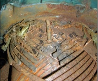
Aqueous (sea water) corrosion and consequent fracture of tensile armour wires close to a breather tube (circled in yellow) in a flexible riser.
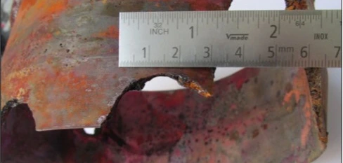
Severe MIC and consequential loss of material from a flexible Corrosion Resistant Alloy (CRA) fitting in a water injection flexible riser.
Having lost much of its section, the fitting finally failed in overload under normal operating conditions
Tools used to identify corrosion mechanisms
Charles Taylor works closely with specialised engineering consultancy Minton Treharne Davies. Its laboratories in Cardiff have access to multiple testing techniques, to help identify the root cause of a corrosion failure.
These include but are not limited to:
- Visual and microscopic examination of fracture faces (fractography) in the tensile armour wires. This can identify if the failure was as a result of general aqueous corrosion or pitting corrosion. The morphology of the corrosion can indicate if the cause was corrosion fatigue, MIC or oxygen/chloride pitting.
- Energy dispersive x-ray analysis of the corrosion product can identify elements which may have been influential in the failure such as carbon, oxygen, sulphur and/or chlorine.
- Inductively coupled plasma optical emission spectroscopy (ICP OES) and gas chromatography mass spectroscopy (GCMS) can both be used to detect parts per billion of specific elements in corrosion products and identify those that may have been influential in the onset and propagation of corrosion that led to a failure.
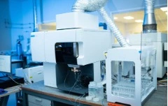
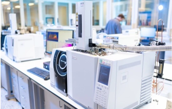
ICP OES and GCMS equipment at MTD’s Cardiff laboratories
Microbial testing and epifluorescence microscopy can reveal if bacteria have been active during corrosion, indicating the possibility of MIC. Combined with DNA testing it is usually possible to identify exactly which type of MIC is the culprit.

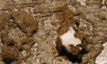
Sulphur Reducing Bacteria (left) and resultant Microbially Influenced Corrosion (right)
- Tensile testing of the armour wires can reveal if the material properties of the wire are consistent with the specified requirement, and also if the wires have become embrittled by hydrogen/sulphur corrosion and/or suffered corrosion fatigue.
Testing in action
In one example of embrittlement, an incorrect grade of steel was used in a flexible riser designed for ‘sweet’ service which was actually used in ‘sour’ service. The ultimate tensile strength should have been less than 1,000MPa, but testing showed it to be in excess of 1,400MPa.
In combination with hardness testing, which can be used to indicate if the tensile armour wires are susceptible to hydrogen embrittlement, MTD demonstrated that the manufacturing was not to the required specification.
Throughout the testing procedure it is important to review design, manufacturing and operational documentation to correlate the testing data with potential sources of corrosive elements and compounds. Combining this knowledge with the testing results allows investigators to zero in on the root cause whilst eliminating other possibilities.
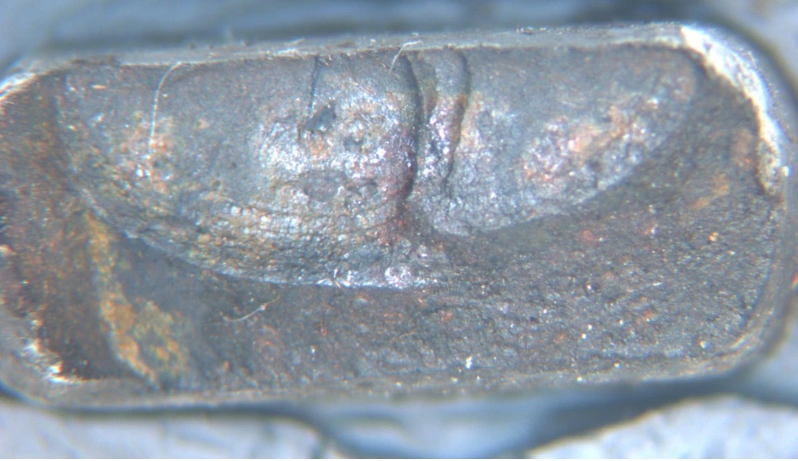
Image of a corrosion fatigued, armour wire, after acid
Final word
In the event of a claim, insurers will seek to limit their liability for losses which arise from corrosion. In many cases where corrosion is a factor in the loss, it is essential for the appointed experts to determine whether the corrosion itself is the cause of the loss (i.e., normal corrosion which may be expected with continued service) or whether it is the effect of some other cause.
Reaching these conclusions requires specific technical expertise and the associated detailed forensic analysis is a highly valuable part of the overall claim process. It is this level of specialised experience and expertise that Charles Taylor and its network of trusted partners provide to insurers.

Mike McMahon
Managing Director, Upstream Energy – Natural Resources
mike.mcmahon@charlestaylor.com

Chris Minton
Company Director, MTD
chris.minton@minton.com

Jeremy Allen
Consultant Materials Scientist, MTD
jeremy.allen@minton.com

